


Irrigation Installation Manual: How to Install a Drip Irrigation System Step by Step (Free PDF)
An irrigation system works well in the field only if installation follows the right sequence with the right parts, just as much as it depends on design. A correctly sized main line leaks because of one badly glued socket; a well-chosen emitter clogs because it was fitted before the lateral was flushed. That is why, on large projects, Perge Engineering gives the installation crew a 3D, step-by-step irrigation installation manual together with the drawings. This article explains what the manual covers and shares a sample manual as a free PDF.
Short answer: An irrigation installation manual is a field document that guides the crew through infrastructure, superstructure and automation in order, showing at every step the part to use, its size, the setting and the test criterion. In Perge’s manual, drawings are 3D views modelled from real catalogue dimensions.
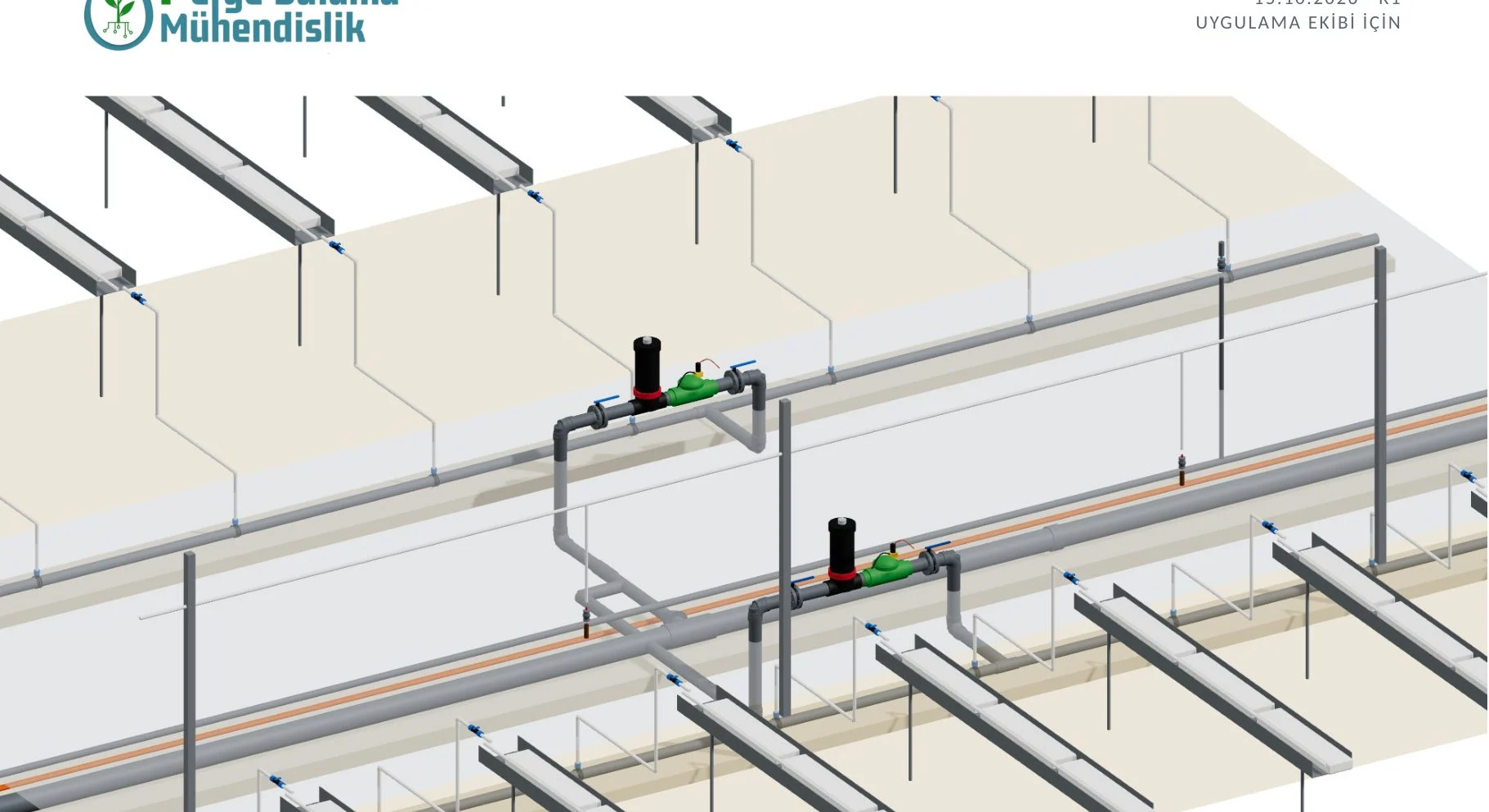
What is an irrigation installation manual and who is it for?
The manual is derived from the irrigation design and the bill of materials; its source documents are the project drawings and the catalogues of the manufacturers used. Its readers are the installation foreman and the fitters on site, so the language is short, the visuals dominate and each page covers one installation step. It is also useful to the investor: it shows in advance how installation will proceed, which tests will be done and what will be checked at handover. The sample manual is in Turkish; manuals for international projects can be prepared in the project language.
Sample manual: soilless tomato greenhouse
The sample was prepared for a large greenhouse project growing soilless tomatoes on cocopeat slabs. Client details were removed; the technical content is unchanged.
| Project data | Value |
|---|---|
| Layout | 2 blocks × 26 tunnels, about 92,500 m² |
| Irrigation layout | 16 sectors, 2 automation rooms |
| Laterals | 624 × 88 m, 25 mm |
| Emitters | 274,560 drip sets, 2.2 L/h pressure-compensated |
| Valve groups | 16 × 3″ groups with bypass |
| Shift flow | 2 × 75.5 m³/h |
| Main line | 510 m Ø160 PVC |
What is in the manual?
The 19-page manual has 15 sections that follow the real installation sequence:
| Section | Topic |
|---|---|
| 01 | Getting to know the system: layout, water path, shift plan |
| 02 | Installation sequence, crew and tools |
| 03–04 | Material identification: PVC pipe and fittings, PE compression fittings, valves, filters, emitters, pump |
| 05 | Step 1 · Setting out and corridor: line positions, trench depths, sand bedding |
| 06 | Step 2 · PVC solvent welding instructions and socket depths |
| 07 | Step 3 · Ø160 main line: laying, tee positions, branches |
| 08 | Step 4 · Valve group: 3″ group with bypass, filter and pressure-reducing solenoid valve |
| 09 | Step 5 · Manifold and lateral connection |
| 10 | Step 6 · Emitter installation |
| 11 | Step 7 · Automation room: pump, inverter, automatic filter |
| 12 | Step 8 · Spraying and clean-water lines |
| 13 | Step 9 · Signal cable |
| 14 | Step 10 · Testing and commissioning |
| 15–16 | Checklist, site acceptance form and staged bill of materials |
Common installation mistakes and how the manual prevents them
Mixing up the stages
The manual splits installation into three stages: infrastructure (setting out, trenching, main line, valve groups, manifolds, signal ducts), superstructure (saddles, laterals, emitters, spraying and clean-water lines) and automation (pump, filter, electrics, controller). The rule is simple: no stage starts until the tests of the previous one are complete.
Poor PVC solvent welding
Most leaks in pressure lines come from poor solvent welding. The manual asks for the same sequence at every joint: cut the pipe square and deburr, clean, mark the socket depth, sand and clean again, then glue. Socket depths are given per diameter, and no pressure test starts before the cement has cured.
Inch–millimetre mismatches
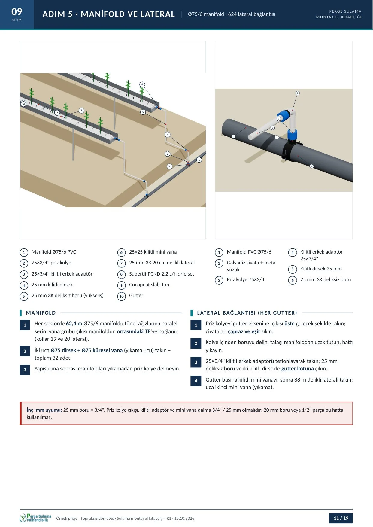
The most frequent part error on site is mixing pipe diameter with thread size. The manual states it plainly: 25 mm pipe takes 3/4″ parts; the saddle outlet, compression adaptor and mini valve must all be the same size. Parts of a different size do not go into the installation.
Fitting emitters before flushing
If drilling swarf or sand left in the line settles on the diaphragm of a pressure-compensated emitter, the emitter clogs, and flushing after the set is fitted cannot clear it. So the sequence in the manual never changes: flush the lateral first, then fit the drip sets.
Commissioning valve groups without setting them
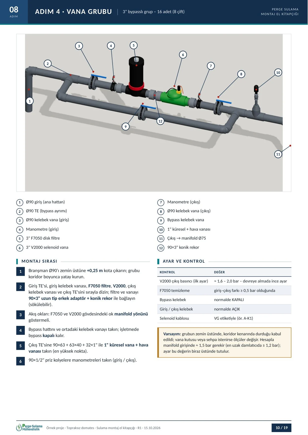
Each valve group has inlet and outlet butterfly valves, two pressure gauges, a disc filter, a pressure-reducing solenoid valve, a bypass and an air valve. The manual gives both the assembly order and the initial settings: in the sample project, about 1.6–2.0 bar initial outlet setting for the solenoid valve, filter cleaning when the inlet–outlet difference reaches 0.5 bar, and the bypass normally closed. Fine-tuning is done during commissioning.
Automation room and pump check
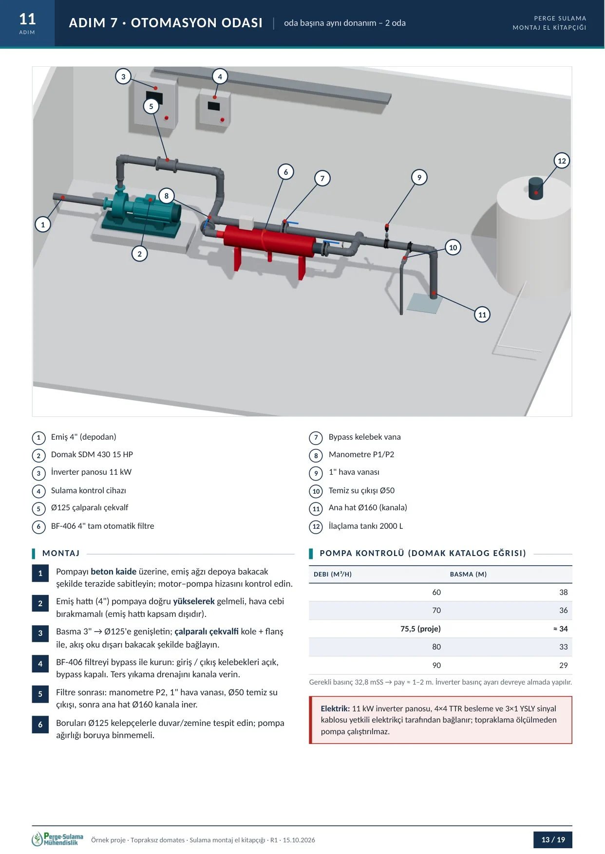
The automation room page shows the layout of the pump, inverter panel, check valve, fully automatic filter, pressure gauges and air valve. The manual compares the pump’s catalogue curve with the project duty point, so the margin between required pressure and the pump head at design flow is visible. It also states that electrical connections must be made by a licensed electrician.
Testing, commissioning and handover
Pressure test recommendations are given section by section, and no test exceeds the pipe pressure class:
| Section | Test pressure | Duration | Acceptance |
|---|---|---|---|
| Ø160 main line + branches | 6 bar | 2 hours | Drop ≤ 0.2 bar, no leaks |
| Valve group + manifold | 4 bar | 1 hour | No leaks |
| Laterals + drip sets | Operating pressure (≈ 2 bar) | 30 minutes | All emitters working |
The final section has a checklist marked separately for infrastructure, superstructure and automation, and a site acceptance form signed by the installation foreman, the Perge supervising engineer and the client. The manual closes with a staged bill of materials, so it is also clear which material must reach the site at which stage.
Download the manual
You can download the sample manual (in Turkish) below. A manual for your own project is built from your design, your bill of materials and the catalogue dimensions of the products used.
Frequently asked questions
Is an installation manual prepared for every project?
It is prepared mainly for large, multi-sector greenhouse and soilless projects where installation is done in stages or by different crews. Its scope is agreed at the quotation stage.
Are the drawings in the manual to scale?
Yes. The drawings are 3D views modelled from the manufacturers’ catalogue dimensions of the products used in the project.
When should emitters be fitted?
After the laterals have been flushed. Drilling swarf and sand can clog the diaphragm of a pressure-compensated emitter, and flushing after fitting cannot clear it.
How is the main line pressure test done?
The sample manual recommends 6 bar for 2 hours with a maximum drop of 0.2 bar for the main line and branches. Test pressure never exceeds the pipe class, and testing does not start before the cement has cured.
What thread size goes with 25 mm pipe?
3/4″. The saddle outlet, compression adaptor and mini valve must be this size; 20 mm pipe or 1/2″ parts must not be mixed into this connection.
How can I request a manual for my own project?
Contact us with your greenhouse layout, crop and water source details. Once the design and bill of materials are final, the manual is prepared from them.
Conclusion
A good irrigation project is finished on paper; a good irrigation system is finished in the field. Perge Engineering closes the gap between the two by running design, supply, installation supervision and commissioning from the same documents. For the design side of soilless strawberry and blueberry irrigation, see our article on soilless strawberry and blueberry irrigation systems, and for completed work, our references.